
Radar PCB
Radar PCB are a type of circuit board that are used in radar sensor systems. They are designed to detect targets using radio frequency (RF) pulses, and thereby, provide velocity, distance, and angle-of-approach information.
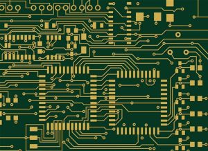
Radar PCBs are fabricated using circuit boards that are designed to pass and filter radio frequency energy. This helps to achieve high efficiency and minimal signal loss.
1. High Stability
Radar PCBs are used in the manufacturing of a wide range of electronic appliances that use radio-frequency technology. These devices are essential for the military as well as aerospace and automotive industries, and require a high level of stability in order to operate properly.
High-frequency circuits require materials that can withstand extreme conditions while maintaining the desired performance. This includes stable dielectric constant and low loss in the circuit. The ability to control these properties ensures that Radar PCBs will provide consistent performance throughout their lifecycle.
These boards are manufactured using a variety of circuit materials, all of which have their own specific requirements when it comes to stability and durability. Rogers RO3003G2 ceramic-filled PTFE(Teflon) laminates are an example of a high-performance material that is designed specifically to meet the needs of millimeter-wave radar applications.
A radar system works by sending out a signal and then detecting the reflected signals from objects. The signal then passes to a digital circuit that analyses it.
Typically, a Radar PCB contains several layers of Radar PCB circuitry that connect with each other through tiny components known as vias. These connections allow different layers of the PCB to be connected in a variety of ways, which can help to reduce the cost of production.
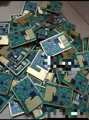
Another important consideration when choosing a Radar PCB is the type of mounting method that it uses. Surface-mounting is a popular choice because it allows for more connections than through-hole mounting. This method also allows for easier access to all the components that make up a Radar PCB.
In addition to a stable dielectric constant and low loss, radar PCBs must also be able to maintain their shape while being subjected to temperature changes. This can be difficult for some circuits, but a stable Radar PCB will have the ability to stay the same size no matter what the environment may be.
2. Low Loss
Radar PCBs are incredibly sensitive to noise, and must have the ability to minimize loss in order to function properly. This is why it is important to use the proper materials to fabricate the circuits on these boards.
These circuits are commonly used in automotive radars and 5G wireless networks, as well as other applications. These devices transmit data at extremely high frequencies, which means they require low-loss materials to minimize noise in the system.
The first step in selecting the right material for a radar PCB is to consider its dielectric constant. A stable dielectric constant is essential for reducing loss in these circuits, as well as ensuring that the materials can maintain their performance over time and under different conditions.
A stable dielectric constant can help reduce the amount of copper foil that will need to be re-worked during fabrication. Smoother copper foil can also be a good choice for minimizing circuit loss.
In addition to a stable dielectric constant, the materials should also be able to withstand time and temperature changes as well as other external working environments. This will help ensure that your product functions effectively and safely for years to come.
The right materials for a radar PCB can be found in the market, but it is crucial to choose a reliable manufacturer. Experienced manufacturers will be able to perform the necessary manufacturing steps efficiently and quickly, and produce quality output.
3. Easily Customizable
Radar PCBs are used in a variety of applications. In addition to being an obvious choice for autonomous driving, they can also be found in everyday devices such as automatic door openers, fire and trespassing alarms, intelligent lights, level meters, and more.
Radar circuits use a number of techniques to determine distance, speed, and even direction. This is accomplished by emitting high-frequency pulses, waiting for a bounce-back signal to return and then sending out another pulse.
Using these high-tech circuits is no easy feat, and it’s no wonder that the highest-quality radar PCBs on the market are more than just a bit fancy.
To create the best-quality radar PCBs, designers must utilize advanced RF design software with a full suite of layout and simulation features. This type of software is the most reliable way to ensure that your radar PCB meets all of its performance specifications and is not subject to the many design mistakes that can occur during manufacturing.
In the end, it’s important to remember that a radar PCB is just Radar PCB one of several electronic components that must be properly assembled before they can perform their intended functions. This means ensuring the correct mounting method and the appropriate materials are used to get the job done.
This is why the best way to find the right Radar PCB for your project is to consult with an experienced RF designer who can advise on the best options for you. They can then help you choose the most cost-effective and functional solution for your specific application.
4. Easily Assembled
Radar PCBs are used in a variety of applications. These include navigation systems, missile guiding, air defense, and enemy identification. They also help in ground traffic control and allow aircraft to land safely on bad weather.
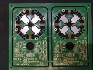
The RF circuit on the front of the radar PCB sends out a signal, which is reflected back by an object. The reflected signal then gets analyzed by the digital circuit on the back of the radar PCB.
This is how the circuit determines the distance between the radar and the target. It also determines the pulse repetition frequency and time. When a radar PCB is sending out a signal, it should be delivered at every clock cycle and the delay between the pulses should be appropriate.
If the delay between the pulses is too long, then the device won’t be able to receive the echo before sending out the next signal. This is why the length of the pulses should be chosen carefully so that you can get a good range.
Similarly, the RF circuit should be designed on a PCB that has low losses. This is important because it prevents the RF circuit from suffering any damage or losing signals.
The combination of materials on a hybrid radar PCB usually includes several layers of low-cost flame-retardant FR-4 circuit material with high glass transition temperature (Tg) and one layer of circuit material that has characteristics well suited for use at higher frequencies. This combination helps to control costs and maintain reliability while meeting the electrical performance requirements of automotive radar sensors at frequencies through 77 GHz.
Radar PCBs have become an essential part of many modern devices. You can find them in almost every car and even homes that have smart lights. They also help in functions like parking and changing lanes.
5. Easily Tested
A radar PCB is a very versatile circuit board that can be used in several different applications. For instance, they can be used in air surveillance equipment, ground traffic control systems, and even spacecraft navigation.
Radar PCBs use high-frequency microwave signals to detect and identify objects. These signals can also be sent through water and air without the need for a wire.
Despite this versatility, designing a Radar PCB can be challenging for some designers. It’s important to consider the operating frequency, component population, board size, and other features when designing.
It’s also important to design a board that’s compatible with the RF circuitry. This is because the RF circuit may influence the layout of the entire radar PCB.
In addition, it’s important to use the right construction material. Radar PCBs that operate at 77GHz millimeter-wave frequencies require different materials than those that operate at lower radio frequencies.
These boards can be difficult to manufacture, but they are essential for autonomous driving systems. They need to be able to detect obstacles and passengers in real time so that the vehicle can make the appropriate decisions.
A good radar PCB manufacturer will be able to provide you with the best quality products for your needs. This is because they will have a wide range of experience in manufacturing RF circuits, and this allows them to produce dependable Radar PCBs that will last for many years.
Another benefit of choosing a reputable Radar PCB manufacturer is that they will be able to offer you a range of testing services for your product. This will allow you to get an accurate idea of how well your radar PCB is working before making a final decision about its performance.